|
|
In the installation guide of the Märklin
Delta decoder 66032 it is mentioned, that "the headlight outputs can
be turned on and off with the digital function "Function" after the appropriate
conversion has been carried out for this purpose." As Märklin
did not mention, how to do this, here you will find the description for
the change. After this change you will have a full replacement for the
older C80 decoder which is not produced any longer. In addition it is shown
how you can convert the additional function to be controlled via F1.
|
Please
note what Märklin is announcing to this theme: If you do any changes
to the electronic equipment of your locomotive by your own, any warranty
is void, so it´s at your own risk. And you cannot get any spare parts
from Märklin (only complete new decoders). Same is with me, I did
the best to avoid any "bugs", but I cannot made liable for any damage occurring
if you follow this text.
|
1. Basics
The Delta decoder 66032 bases on the Motorola 2 Format developed by Märklin. This means for instance setting a loco on the tracks after a longer period of time, the decoder will identify the correct direction selected with the Control Unit. The central chip is the 701.43A. Further features like the functions F2 ... F4 cannot be implemented with this decoder, as far as I know.2. Features and connection of the decoder
The decoder is designed for connection to the conventional 3 pole motor with electric field magnet (with 3 wires: green, blue, black). Further it has the feature to switch one function according to the direction the loco is going, i.e. the head lights. The original decoder has this function always turned on. This is valid for all 3 operating modes: conventional AC, Delta and Digital. With the change, I will describe later, this function can be turned on and off with Digital. With Delta, the behavior is related to the type of central unit you are using and with AC the function is always on, depending on the voltage applied to the loco.The additional function output (for Telex) is switched by repeated change of driving direction (2 times on then 2 times off, and so on). It may be converted so that it is controlled by F1. This works only with Digital. With AC and Delta you cannot control the additional function after the conversion.
This is the first Delta decoder with 8 DIP switches for the address, so it can use the full address space of 80 addresses like a Digital decoder.
This is the decoder connection diagram as supposed by Märklin:
Sorry for the schematic being in German,
"an br, wenn nicht massefrei !" means "this cable must be connected to
brown if not isolated from chassis !". The maximum load for the outputs
are:
|
Engine
|
1000 mA
|
|
|
Lights
|
200 mA
|
|
|
Function
|
250 mA
|
|
|
Sum
of all outputs
|
1200
mA
|
3. The change
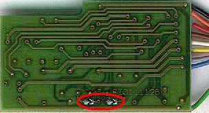
The layout you can see in the next two images, I removed the plastic case around the decoder: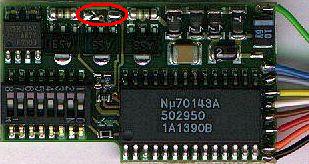
|
Front
|
Rear
|
3.1 Changes for the Function "function"
On the bottom of the rear side you can see two pairs of solder pads. Connect each pair of pads with a small amount of solder and you have done the work. All three pairs of solder pads on the front side remain unchanged. Now the direction related function can be turned on and off with your Control Unit 6021 keys "function" and "off". So this decoder is a full replacement for the older C80 decoder which is not produced any longer.3.2 Changes for controlling the addtional function by F1
On the front side you will find three pairs of solder pads, two of them close to each other at the top of the image between the resitors. If the right pair of solder pads is closed and the left is open, as shown in the image, the additional function is controlled by reversing the direction. If you open the right pair of solder pads ( ) and close the left, the additional function is controlled by F1, which can only be performed by the control unit 6021. Never operate the controller with both solder pad pairs closed.![]()
(c) Jürgen Schad, 03.10.2002